Table of Contents
Introduction
Mining material handling places unusual demands on every load-bearing component. Loads may be dense, irregular, abrasive, difficult to approach, or supported through only a few concentrated contact points. The working surface may be uneven, and equipment may operate through long cycles with frequent shock, vibration, dust, and moisture.
Under these conditions, ordinary pallet forks may not provide the required dimensions, stiffness, mounting arrangement, or resistance to repeated impact. Mining forks are designed for heavier and less predictable handling tasks, including large components, reinforced skids, maintenance equipment, structural materials, machinery parts, and other industrial loads.
The most important mining fork trends in 2026 are not cosmetic changes. They reflect a more disciplined selection process:
- Fork dimensions are increasingly matched to defined load geometry.
- Load center is being evaluated together with nominal load weight.
- Mounting systems are treated as part of the load path.
- Fork pairs are inspected and documented as matched components.
- Wear measurements are recorded instead of relying only on visual judgment.
- Custom designs are based on drawings, support points, and handling sequences.
- Harsh-environment maintenance is planned before the forks enter service.
These priorities matter because a mining fork does more than carry a stated weight. It must enter the load correctly, support it in the intended position, transfer force through the heel and mounting system, and remain inspectable throughout its working life.
A reliable selection process begins with the load, not the apparent size of the fork.
What Are Mining Forks?
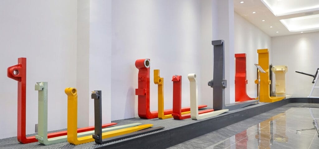
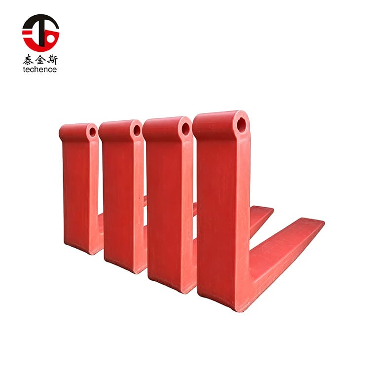
Mining forks are heavy-duty fork arms developed for demanding material-handling environments. They may be installed on large forklifts, loaders, telehandlers, industrial lifting machines, or purpose-built equipment with compatible fork carriages.
They are generally characterized by one or more of the following:
- Large blade cross-sections
- Heavy-duty forged construction
- Longer or customized blades
- Reinforced heels and shanks
- Pin, shaft, hook, or integrated mounting
- Wide fork spacing
- Application-specific tip profiles
- High resistance to impact and repeated loading
- Dimensions based on nonstandard loads
The term mining forks describes the working application rather than one universal shape. A fork designed for underground maintenance equipment may differ from a fork used to handle large surface-operation components.
Typical Applications
Mining forks may be used for:
- Heavy machinery components
- Reinforced material pallets
- Structural steel
- Large tires and wheel assemblies
- Tooling frames
- Maintenance platforms designed for fork handling
- Pipes and bundled profiles
- Industrial motors and gearboxes
- Equipment skids
- Large castings
- Conveyor components
- Drilling and excavation equipment parts
The load must still have structurally suitable support points. When a load lacks safe fork pockets or stable bottom support, another attachment may be required.
Mining Forks vs General-Purpose Forks
General-purpose forks are commonly designed for conventional pallets and relatively standardized load centers. Mining forks often need to handle larger sections, longer loads, uneven centers of gravity, and harsher contact conditions.
The distinction is not based only on capacity. Important differences may include:
- Blade thickness
- Blade width
- Fork length
- Heel geometry
- Shank construction
- Mounting type
- Tip profile
- Steel grade
- Heat-treatment process
- Inspection requirements
A standard fork with a high stated capacity is not automatically a mining fork.
Mining Forks vs Loader Attachments
A loader bucket, rock fork, grapple, and mining fork perform different tasks.
Mining forks are intended to support suitable loads from below. Buckets are generally used for loose material. Grapples provide additional retention for irregular materials, while specialized cradles or clamps control loads that cannot rest safely on flat fork blades.
The correct attachment depends on the load’s physical form and approved handling method.
Why Mining Operations Need Specialized Forks
The conditions associated with mining create a combination of structural, environmental, and operational challenges.
Concentrated Loads
A heavy load may rest on two narrow steel rails, a pair of machine-frame supports, or small reinforced fork pockets.
This creates high local pressure on the fork blades. Two loads with the same total weight can produce very different fork stresses when their contact areas differ.
When documenting a load, record:
- Number of support points
- Width of each support
- Distance between supports
- Contact material
- Position along the blade
- Whether the supports can bend
- Whether the load can shift during travel
Total load weight alone does not describe the complete loading condition.
Irregular Centers of Gravity
Mining and maintenance equipment often contains dense components positioned away from the geometric center.
Motors, transmissions, hydraulic assemblies, counterweights, and stored materials may shift the center of gravity toward one side or one end.
An off-center load can place more force on one fork and one side of the carriage. The fork pair must therefore be selected and positioned around the real center of gravity.
Impact and Shock Loading
Fork tips and blades may strike:
- Steel frames
- Skids
- Equipment supports
- Floor edges
- Loading platforms
- Stored materials
- Vehicle structures
Impact produces a different load from steady lifting. A fork that carries a static load successfully may still be damaged by repeated high-energy contact.
The solution is not simply to make every fork larger. Fork geometry, material toughness, tip design, operator procedure, approach visibility, and load access must all be considered.
Abrasive Contamination
Dust, grit, mineral particles, and metal fragments can accumulate around fork hooks, pins, locks, and carriage bars.
Abrasive contamination may:
- Increase mounting wear
- Restrict fork positioning
- Hide surface cracks
- Damage protective finishes
- Accelerate corrosion
- Create false measurements
- Prevent locks from engaging fully
Cleaning is therefore part of structural inspection, not only housekeeping.
Uneven Surfaces
Uneven ground changes the relative height of the two fork tips and affects the operator’s approach angle.
One fork may contact the load first, creating twisting, side loading, or unequal insertion. The machine may also lean while carrying the load.
Fork suitability should be tested on the actual travel route, not only on a level workshop floor.
Repetitive Heavy-Duty Cycles
A fork used occasionally experiences a different fatigue history from one used throughout continuous production and maintenance cycles.
High-cycle operation increases the importance of:
- Heel inspection
- Blade-thickness measurement
- Pair alignment
- Mounting wear
- Impact reporting
- Carriage inspection
- Traceability
- Scheduled replacement criteria
Mining Fork Trends Shaping Selection in 2026
The following trends represent practical changes in how demanding fork applications are being specified and managed.
Trend 1: Load Geometry Is Replacing Generic Capacity Descriptions
A request such as “heavy forks for a large machine” is not enough for accurate selection.
A complete specification now needs:
- Maximum weight
- Load depth
- Load width
- Center of gravity
- Support locations
- Fork-pocket dimensions
- Lift height
- Required fork spacing
- Operating surface
- Mounting dimensions
This reduces the risk of choosing a fork that has sufficient nominal capacity but unsuitable geometry.
Trend 2: Load Center Is Receiving More Attention
Long mining components can move the center of gravity well beyond the condition used for the machine’s original rating.
As the horizontal distance increases, the forward load moment increases even when the load weight remains unchanged.
This makes load-center verification essential for long machinery frames, pipes, structural assemblies, and equipment skids.
Trend 3: Fork Weight Is Included Earlier in Capacity Reviews
Mining forks may be significantly heavier than standard forks.
Their weight becomes part of the load carried in front of the machine and may reduce residual capacity. Large blade sections and long lengths should therefore be justified by the application.
The strongest-looking fork can become counterproductive when unnecessary weight reduces the usable capacity of the complete configuration.
Trend 4: Mounting Systems Are Treated as Structural Components
Hooks, pins, shafts, locks, and carriage bars transfer the load into the mast or machine frame.
A new fork installed on a worn carriage can remain loose, misaligned, or unevenly loaded.
Current selection practice increasingly evaluates the complete fork-to-carriage interface rather than treating mounting dimensions as a secondary detail.
Trend 5: Customization Is Becoming More Data-Driven
Custom mining forks are most effective when designed from verified information.
Useful inputs include:
- Load drawings
- Equipment drawings
- Fork-pocket measurements
- Center-of-gravity information
- Current fork dimensions
- Photographs with scale references
- Carriage dimensions
- Handling videos
- Travel-route conditions
- Operating cycle frequency
Customization should remove uncertainty, not introduce undocumented changes.
Trend 6: Inspection Is Moving Toward Recorded Measurements
Visual checks remain essential, but gradual wear can be difficult to judge without reference data.
More structured programs record:
- Blade thickness
- Fork-tip height difference
- Hook opening
- Pin diameter
- Mounting-eye wear
- Fork straightness
- Heel condition
- Impact events
- Corrosion areas
- Installation and inspection dates
Trend records can reveal deterioration before the fork reaches an obvious failure condition.
Start with the Actual Mining Load
The first engineering task is to define what the forks must support.
Maximum Load Weight
Record the total operating weight, including:
- Main equipment
- Packaging
- Skids
- Frames
- Retained fluids
- Tools
- Fixtures
- Accessories
- Protective structures
Use the maximum approved load rather than the average load.
Load Dimensions
Measure:
- Overall width
- Overall depth
- Overall height
- Fork-pocket width
- Fork-pocket height
- Distance between fork pockets
- Distance from the fork face to the load center
- Required insertion depth
- Maximum permitted fork projection
These measurements determine whether the forks can enter, support, and release the load correctly.
Center of Gravity
The center of gravity may be marked on machinery drawings or transport documentation. When it is not available, it should be established through an approved technical process.
Do not assume that the center of gravity lies halfway along the load.
Support-Point Position
Document where the load will actually rest on the blades.
If the supports are positioned near the fork tips, review whether:
- The forks are too short
- Insertion is blocked
- The load center is excessive
- The pockets are poorly located
- Another handling orientation is available
The thinner tip section should not become the primary carrying area.
Load Variability
A fork pair may handle several load types during one shift.
Include the most demanding approved examples:
- Heaviest load
- Longest load
- Most concentrated load
- Most uneven load
- Smallest fork pockets
- Greatest center-of-gravity offset
- Highest required lift
- Most difficult approach
Choose the Correct Mining Fork Dimensions
The main dimensions must work together. Selecting each dimension independently can create a fork that fits one requirement but fails another.
Fork Length
Forks should be long enough to support the load properly without projecting farther than necessary.
Forks that are too short can cause:
- Incomplete support
- Tip loading
- Increased load center
- Load instability
- Damage to skids or pockets
Forks that are unnecessarily long can cause:
- Reduced maneuverability
- Increased fork weight
- Greater deflection
- Contact with nearby structures
- Poor visibility
- Unnecessary forward projection
Blade Width
A wider blade distributes contact over a larger area, but it must fit the load opening.
Check internal restrictions such as:
- Weld beads
- Reinforcing plates
- Fasteners
- Bent pocket walls
- Debris
- Surface scale
The usable opening may be smaller than its external dimensions suggest.
Blade Thickness
Thickness contributes to stiffness and load capacity, but an oversized blade may not enter the load pocket.
A thicker blade may also raise the load during entry and increase the fork’s own weight.
The correct thickness balances:
- Capacity
- Deflection
- Entry clearance
- Weight
- Material properties
- Blade width
- Fork length
- Load-center condition
Fork Spacing
Fork spacing should place the blades beneath structurally suitable load areas.
Forks positioned too close together may provide poor lateral stability. Forks positioned too far apart may contact weak supports or exceed the carriage’s stable working width.
Tip Profile
Mining fork tips may use:
- Standard tapers
- Reinforced tips
- Polished entry surfaces
- Application-specific tapers
- Reduced-width tips
- Custom entry geometry
A thin tip can improve entry but may be less suitable where repeated impact is unavoidable. Tip selection should reflect both clearance and duty conditions.
Heel and Shank Geometry
The heel transfers force from the horizontal blade into the vertical shank.
Important design features include:
- Smooth heel radius
- Consistent section transition
- Accurate blade-to-shank angle
- Suitable heat treatment
- Absence of sharp machining marks
- Correct mounting relationship
The shank must match the mounting system and provide sufficient structural support.
Understand Capacity and Load Center
The capacity of the complete machine cannot be determined from the fork rating alone.
Nominal Capacity
Nominal capacity describes performance under defined conditions. Those conditions may include a particular load center, fork position, mast configuration, and lift height.
Changing the fork length, weight, or load position can change the usable capacity.
Residual Capacity
Residual capacity is the amount the complete machine can safely handle after considering:
- Mining fork weight
- Load center
- Mast
- Lift height
- Carriage
- Attachments
- Machine geometry
- Load dimensions
- Operating configuration
A higher-capacity fork does not increase the approved capacity of the machine.
Uneven Fork Loading
A stated pair capacity usually assumes the load is distributed appropriately between the two forks.
One fork may carry more load when:
- The center of gravity is offset
- The approach is misaligned
- Fork spacing is incorrect
- One pocket is higher
- The load is tilted
- The supports differ in stiffness
- One fork enters farther
The loading condition should be corrected rather than relying on the apparent strength of one blade.
Match Mining Forks to the Machine and Carriage
The mounting system is part of the structural load path.
Hook-Type Mining Forks
Hook-type forks connect to upper and lower carriage bars.
Verify:
- Carriage class
- Upper-hook opening
- Lower-hook position
- Shank height
- Hook width
- Lock-pin location
- Carriage-bar dimensions
- Side clearance
The hooks must seat fully and remain secured by a functioning locking system.
Pin-Type Mining Forks
Pin-type forks hang or pivot from a large pin or shaft.
Important measurements include:
- Pin diameter
- Mounting-eye diameter
- Eye width
- Distance between mounting points
- Pin material
- Retainer arrangement
- Side clearance
- Supporting-frame geometry
Pin wear and eye wear should be assessed together.
Shaft-Mounted Forks
Shaft-mounted designs may allow the forks to move laterally along a support shaft.
The shaft, fork eyes, retainers, end stops, and positioning system must be evaluated as a complete assembly.
Integrated Carriages
Some heavy-duty machines use custom carriages in which the fork mounting is integrated with a positioning or support frame.
In these cases, the fork cannot be selected from machine capacity alone. Detailed interface drawings may be required.
Locks and Retainers
Small retaining components can have a critical function.
Inspect:
- Lock pins
- Stops
- Retaining plates
- Pin clips
- Shaft collars
- Bolts
- Carriage notches
- Welded retainers
A strong fork with an incomplete retaining system is not a safe configuration.
Evaluate Material and Manufacturing Quality
Mining fork performance depends on how the complete component is manufactured, not simply on its finished dimensions.
Steel Selection
The steel must provide a suitable balance of:
- Strength
- Toughness
- Fatigue resistance
- Impact tolerance
- Heat-treatment response
- Environmental durability
Higher hardness is not always better. Excessive hardness can reduce resistance to severe impact, while insufficient strength can increase permanent deformation.
Forging
Forging shapes the material under controlled force and can create a continuous load-bearing form through the blade, heel, and shank.
Properly manufactured mining forks can be produced in different blade sections and lengths to match heavy-duty load and machine requirements.
Forging quality should be supported by material records, process control, heat treatment, dimensional inspection, and final examination.
Heat Treatment
Heat treatment influences strength, toughness, hardness, and fatigue behavior.
Important controls include:
- Heating temperature
- Soaking time
- Cooling process
- Tempering
- Section thickness
- Distortion control
- Batch consistency
- Final mechanical properties
Large fork sections require particular attention because different areas may heat and cool at different rates.
Heel Formation
The heel is one of the most highly stressed fork areas.
Inspect for:
- Smooth radius
- Consistent thickness
- Correct angle
- Surface cracks
- Deep grinding
- Heat marks
- Unapproved welding
- Abrupt transitions
Dimensional Accuracy
A matched fork pair should have consistent:
- Length
- Blade width
- Blade thickness
- Tip height
- Taper
- Heel angle
- Mounting position
- Shank geometry
Unequal forks can support the load unevenly even when both components are individually strong.
Traceability
Useful documentation may include:
- Fork identification
- Drawing number
- Revision
- Material batch
- Heat-treatment batch
- Capacity condition
- Load-center condition
- Inspection results
- Manufacturing date
- Mounting dimensions
Mining Forks Compared with Other Fork Types
| Fork or Attachment Type | Best-Suited Application | Main Advantage | Main Limitation |
|---|---|---|---|
| Standard forks | Conventional pallets and routine industrial loads | Simple, versatile, and widely compatible | May lack the section or geometry required for severe mining duty |
| Mining forks | Dense, irregular, heavy, or specialized mining loads | Heavy-duty construction matched to harsh conditions | Greater weight and need for detailed technical verification |
| Port forks | Large cargo, industrial skids, and heavy terminal handling | Long and large-section designs for major cargo | May not match mining-machine mounting or impact conditions |
| Full taper forks | Low-clearance pallet or skid entry | Thin, gradual entry profile | Not automatically suitable for severe impact or concentrated heavy loads |
| Fork extensions | Occasional approved handling of longer loads | Temporary increase in support length | Do not replace purpose-designed mining forks |
| Pin-type forks | Heavy machines using shaft or pin mounting | Strong mounting suited to specialized carriages | Requires exact pin, eye, and retention dimensions |
| Loader rock forks | Separating or carrying loose coarse material | Open structure allows smaller material to fall through | Not intended for supporting conventional unit loads |
| Custom cradle | Cylindrical or shaped equipment | Provides form-fitting load support | Less versatile and must match the load geometry |
| Clamp attachment | Loads requiring lateral retention | Controls loads that cannot rest safely on flat blades | Requires correct pressure, contact surfaces, and hydraulic capacity |
The choice should follow the approved handling method. A mining fork is appropriate only when bottom support through fork blades is suitable for the load.
Use the ROCKS Mining Fork Selection Framework
The following original framework combines the major selection priorities into five stages.
R: Real Load Data
Collect:
- Maximum weight
- Dimensions
- Center of gravity
- Support locations
- Fork-pocket dimensions
- Load variability
- Required lift height
- Handling frequency
A fork should not be selected until the real load is defined.
O: Operating Environment
Review:
- Ground condition
- Dust and contamination
- Moisture
- Corrosive exposure
- Temperature variation
- Impact frequency
- Visibility
- Travel route
- Shift length
- Cleaning access
C: Carriage and Capacity
Confirm:
- Machine model
- Carriage type
- Mounting dimensions
- Fork spacing
- Locking system
- Fork weight
- Residual capacity
- Mast clearance
- Installed attachments
Compatibility and capacity are mandatory gates, not scoring preferences.
K: Key Manufacturing Controls
Evaluate:
- Material specification
- Forging process
- Heat treatment
- Heel formation
- Dimensional accuracy
- Fork-pair consistency
- Identification
- Inspection records
- Traceability
S: Service and Inspection Plan
Define:
- Daily checks
- Detailed inspection intervals
- Wear-measurement points
- Cleaning procedures
- Corrosion protection
- Impact reporting
- Carriage inspection
- Removal-from-service criteria
Conduct a Controlled Handling Trial
A controlled trial verifies whether the proposed mining forks work in the real operation.
Select Representative Loads
Include:
- Heaviest approved load
- Longest load
- Greatest load center
- Smallest fork pockets
- Most concentrated support
- Most uneven center of gravity
- Most difficult approved travel route
- Typical daily load
Test Fork Entry
Observe whether:
- Both forks enter evenly
- The tips contact pocket walls
- Full insertion is possible
- Visibility is adequate
- The load shifts during entry
- Excessive tilt is required
- The fork spacing supports the intended structure
Test the Initial Lift
Raise the load only enough to confirm support.
Check:
- Load balance
- Fork deflection
- Unequal blade loading
- Mounting movement
- Carriage noise
- Load-support position
- Packaging or frame deformation
Test Controlled Travel
Observe the load during:
- Starting
- Braking
- Turning
- Surface transitions
- Mast tilt
- Placement
- Lowering
The trial should use the intended route and working conditions.
Inspect After Testing
After unloading, inspect:
- Tips
- Blade contact areas
- Heel
- Shank
- Hooks or pins
- Locks
- Carriage
- Load pockets
- Skid or frame
- Any surface marks
A single successful cycle is not enough. Performance should be repeatable.
Inspect Mining Forks in Daily Service
Mining forks should receive both routine visual checks and scheduled detailed inspections.
Fork Tips
Look for:
- Upward or downward bending
- Chipped corners
- Deep gouges
- Burrs
- Unequal shape
- Impact marks
- Excessive wear
Tip damage often indicates poor alignment, restricted entry, or repeated ground contact.
Blade Wear
Measure the underside and primary contact areas at fixed locations.
Abrasive wear may occur gradually and remain difficult to judge visually.
Heel Condition
Check for:
- Cracks
- Deformation
- Heat discoloration
- Grinding
- Unapproved welding
- Surface lines
- Changes in angle
The heel should receive particular attention after overload or severe impact.
Mounting Components
Inspect:
- Hooks
- Pins
- Eyes
- Shafts
- Locks
- Retainers
- Carriage bars
- Fasteners
- End stops
Contamination should be removed before assessing wear.
Fork-Pair Alignment
Compare:
- Tip height
- Blade angle
- Length
- Taper
- Hook position
- Shank position
- Straightness
A significant difference may indicate bending, twisting, mounting wear, or an unmatched replacement.
Identification
Capacity and identification markings should remain readable.
Missing or unclear information makes future inspection and replacement more difficult.
Maintain Mining Forks in Harsh Conditions
Maintenance should address the conditions that accelerate structural deterioration.
Remove Abrasive Contamination
Clean around hooks, pins, locks, carriage bars, shafts, and sliding areas.
Do not allow compacted material to prevent full mounting engagement.
Control Corrosion
Clean and protect exposed surfaces while keeping inspection areas visible.
Heavy coatings should not conceal cracks, grinding marks, or deformation.
Protect Mounting Interfaces
Wear between the fork and carriage can create movement that increases impact and uneven loading.
Inspect both sides of every interface instead of replacing only the fork.
Record Impact Events
Operators should report severe contact, dropped loads, overload events, collisions, and unusual fork movement.
The forks may need inspection even when no immediate damage is visible.
Measure Wear Consistently
Use the same measurement locations and methods during each scheduled inspection.
Consistent records are more valuable than isolated estimates.
Common Mining Fork Selection Mistakes
Choosing by Machine Capacity Alone
The machine rating does not define the correct fork length, section, mounting, or load center.
Selecting Unnecessarily Long Forks
Extra length adds weight and may increase deflection and forward projection.
Use the shortest fork that provides complete approved support.
Ignoring Concentrated Support Loads
A narrow steel support can create more local stress than a wide skid carrying the same total weight.
Assuming Heavy-Duty Forks Are Universal
Mining forks vary in dimensions, material, mounting, tip design, capacity conditions, and intended duty cycle.
Using Fork Extensions as Permanent Mining Forks
Extensions may be appropriate for occasional approved loads, but they do not automatically provide the structural behavior of purpose-built long mining forks.
Replacing Only One Fork
The new and remaining forks must be compared for:
- Length
- Section
- Capacity
- Mounting
- Tip height
- Wear
- Taper
- Shank angle
Ignoring Carriage Wear
New forks cannot correct a damaged pin, worn carriage bar, enlarged mounting eye, or defective lock.
Continuing After Severe Impact
A fork can contain damage that is not immediately obvious.
Severe impact should trigger inspection before the equipment returns to full-duty operation.
Mining Fork Specification Checklist
Prepare the following information before requesting a fork recommendation.
Machine Information
- Machine manufacturer and model
- Equipment identification
- Rated capacity
- Rated load center
- Mast or lifting structure
- Maximum lift height
- Carriage type
- Mounting dimensions
- Current fork dimensions
- Installed attachments
- Previous modifications
Load Information
- Maximum load weight
- Load width, depth, and height
- Center-of-gravity location
- Fork-pocket dimensions
- Support-point locations
- Packaging or frame type
- Load variation
- Handling frequency
Operating Information
- Ground condition
- Dust exposure
- Moisture exposure
- Impact frequency
- Travel route
- Visibility limitations
- Number of cycles
- Storage arrangement
- Inspection interval
Required Fork Information
- Length
- Width
- Thickness
- Tip profile
- Fork spacing
- Mounting type
- Locking system
- Surface requirements
- Identification requirements
- Documentation requirements
When the load, mounting system, or duty cycle falls outside a standard configuration, a custom mining fork specification review should include drawings, photographs, measurements, center-of-gravity information, and the complete handling sequence.
Conclusion
Mining forks are designed for environments where heavy loads, impact, abrasive contamination, uneven surfaces, and long duty cycles create demands beyond ordinary pallet handling.
A reliable mining fork specification should not begin with a capacity number alone. It should begin with the real load, its center of gravity, support points, fork pockets, handling height, machine configuration, and operating environment.
The most important selection principles are:
- Define the complete load.
- Verify the real load center.
- Choose only the necessary fork length and section.
- Match the fork to the actual carriage.
- Evaluate material, forging, heat treatment, and heel quality.
- Treat the fork pair as a matched system.
- Conduct a controlled handling trial.
- Record wear and impact throughout service.
The largest mining forks are not automatically the most reliable. The correct forks are those that fit the machine accurately, support the load in the intended position, remain within verified residual capacity, and tolerate the real working conditions without introducing unnecessary weight or complexity.
FAQ
What are mining forks used for?
Mining forks handle heavy machinery parts, reinforced skids, structural materials, motors, gearboxes, conveyor components, tooling frames, and other dense industrial loads. The cargo must have stable support points or suitable fork pockets for safe bottom lifting.
How are mining forks different from standard forks?
Mining forks normally use larger blade sections, heavier mounting systems, application-specific dimensions, and materials selected for impact and repeated loading. Standard forks are generally intended for more predictable pallets, load centers, and operating surfaces.
How do I choose the correct mining fork length?
Measure the load depth, support-point position, insertion requirement, load center, and available maneuvering space. Select the shortest length that provides complete approved support without carrying the load near the tips or projecting unnecessarily beyond it.
Can mining forks fit any heavy-duty machine?
No. The fork must match the carriage, hook, pin, shaft, eye, lock, spacing, mast clearance, and residual machine capacity. Similar machine capacities do not prove that the mounting systems or fork dimensions are interchangeable.
How often should mining forks be inspected?
Complete a visual check before use and schedule detailed inspections according to impact exposure, duty cycle, contamination, corrosion, load severity, manufacturer guidance, and applicable requirements. Severe impact or overload should trigger an additional inspection.