Table of Contents
Introduction
Heavy cargo rarely behaves like an ordinary warehouse pallet. It may be longer, denser, less balanced, more difficult to approach, or supported by only a few structural points. When a forklift handles industrial machinery, steel products, heavy skids, large unit loads, or breakbulk cargo, standard fork dimensions may not provide the required support or durability.
Port forks are designed for these demanding handling conditions. They generally use larger blade sections, reinforced load paths, heavy-duty mounting arrangements, and dimensions selected around the actual cargo rather than a standard pallet format.
The name comes from their common use in port terminal operations, where cargo may move between storage areas, loading platforms, transport equipment, and staging zones. However, their usefulness is not limited to waterfront facilities. Similar forks can be used wherever heavy, long, or concentrated loads require a more substantial fork design.
Port forks should not be selected simply because a forklift has a high nominal capacity. The complete configuration must account for:
- Maximum load weight
- Load dimensions and center of gravity
- Fork length, width, and thickness
- Load-support position
- Fork spacing
- Fork and carriage weight
- Lift height
- Mast configuration
- Mounting method
- Surface conditions
- Impact and duty cycle
- Inspection and maintenance requirements
The most effective design is not necessarily the largest fork available. It is the fork that supports the real load correctly, fits the forklift securely, maintains verified residual capacity, and performs consistently in the actual operating environment.
What Are Port Forks?
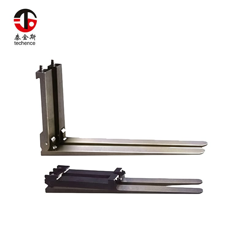
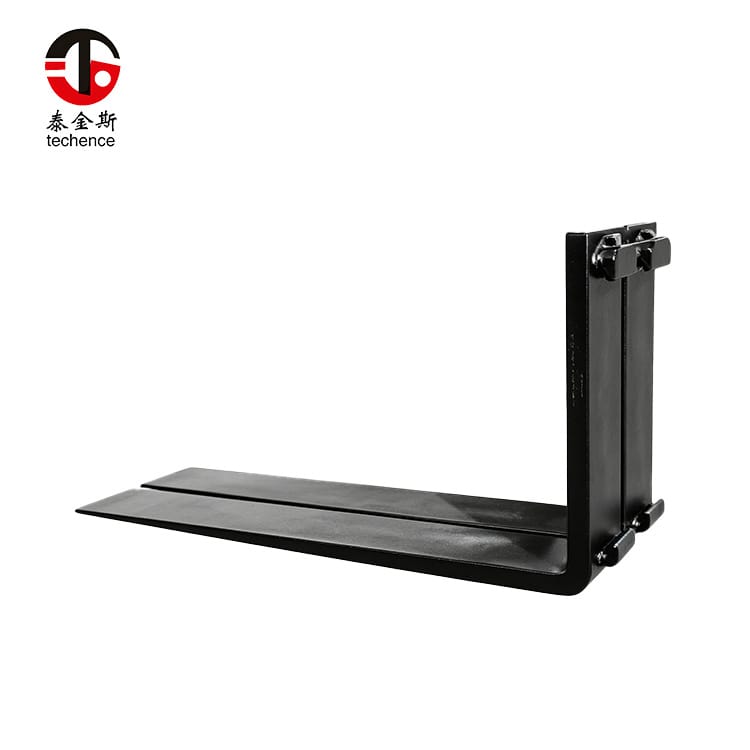
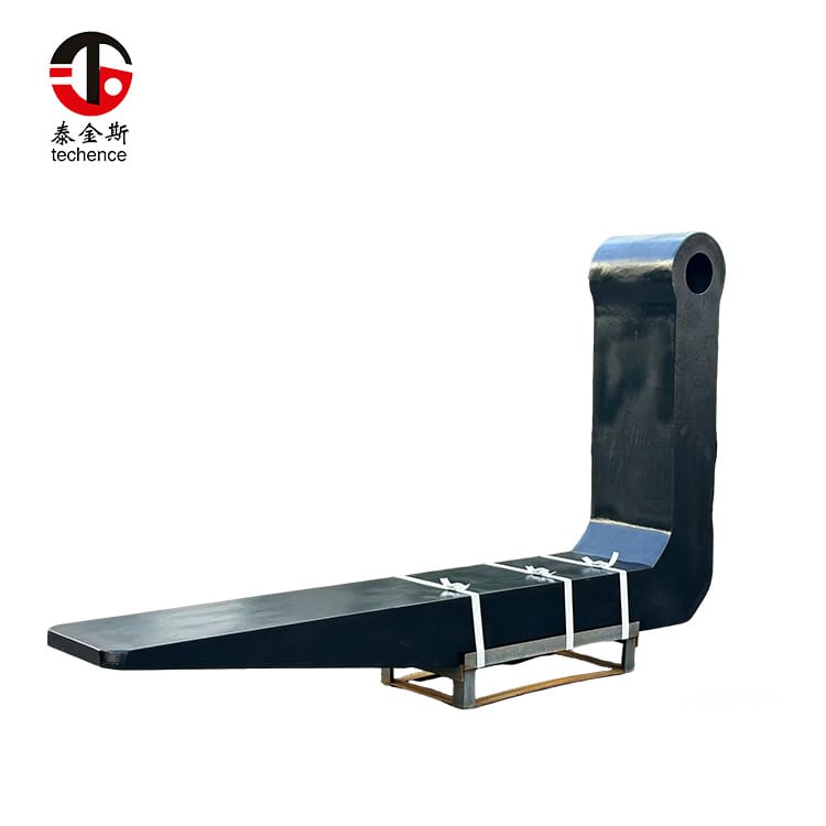
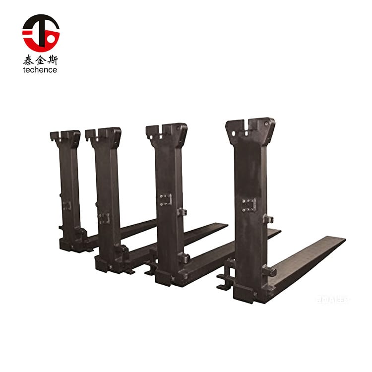
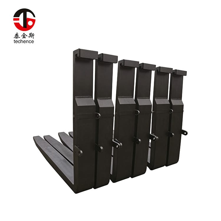
Port forks are heavy-duty fork arms engineered for demanding cargo-handling applications. They are typically installed on high-capacity forklifts, heavy industrial trucks, terminal tractors with lifting systems, or purpose-built material-handling machines.
Their construction may include:
- Large blade cross-sections
- Extended blade lengths
- Reinforced heels
- Heavy shanks
- Hook, pin, shaft, or integrated mounting
- Custom fork spacing
- Application-specific tip profiles
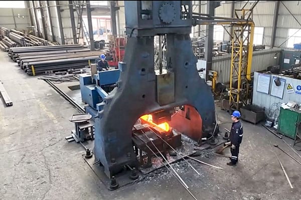
- Forged or carefully formed load-bearing sections
Unlike general warehouse forks, port forks are often specified around an individual load family or operating process.
Heavy-Duty Fork Construction
The load carried by a fork creates bending stress along the blade and concentrated stress around the heel. As load weight, load center, and fork length increase, these stresses become more demanding.
A port fork therefore needs a continuous structural path from the blade through the heel and into the shank or mounting system.
A large external size alone does not guarantee suitable performance. Material properties, forging quality, heat treatment, heel geometry, dimensional accuracy, and surface condition all affect the final result.
Typical Port and Terminal Applications
Port forks may be used to handle:
- Heavy pallets
- Industrial machinery
- Steel plates
- Metal bundles
- Large castings
- Heavy crates
- Structural components
- Long skids
- Project cargo
- Unitized breakbulk loads
- Heavy containers or frames designed for fork handling
- Equipment with dedicated fork pockets
The load must still provide appropriate support points. A heavy object without suitable fork-entry areas may require a cradle, lifting beam, clamp, spreader, or another engineered attachment.
Port Forks Are Not Container Spreaders
Port forks and container spreaders perform different functions.
Port forks support cargo from below. They enter fork pockets, pallet openings, skids, frames, or spaces beneath a load.
A container spreader normally engages designated lifting points from above. It is designed around a different lifting method and load path.
Large port forks should not be assumed to lift every cargo container directly. The load must be designed or approved for fork engagement, and the selected support points must tolerate the contact forces.
This distinction prevents a common selection error: choosing a larger pair of forks for a load that actually requires a different lifting system.
What Types of Loads Are Suitable for Port Forks?
Port forks work best when the cargo has stable, accessible, and structurally suitable support points.
Unitized Heavy Cargo
A unitized load is arranged so that multiple items behave as one handling unit.
Examples include:
- Strapped metal bundles
- Secured machinery on skids
- Reinforced crates
- Wrapped industrial components
- Heavy products fixed to a transport frame
The unitization method must remain secure during fork entry, lifting, travel, braking, turning, and placement.
Steel and Metal Products
Steel plates, bars, profiles, coils, castings, and fabricated assemblies can create concentrated loading.
When handling metal cargo, check:
- Contact-point position
- Load stiffness
- Surface friction
- Sharp edges
- Load deflection
- Risk of sideways movement
- Required fork spacing
- Protection of the fork surface
- Protection of the product surface
A heavy load distributed across a wide skid behaves differently from the same weight concentrated on two narrow supports.
Industrial Machinery
Machinery may have an uneven center of gravity because major components such as motors, gearboxes, pumps, counterweights, or frames are positioned on one side.
The external dimensions do not always reveal the true balance point.
Before handling machinery, identify:
- Approved lifting or fork-entry points
- Center-of-gravity markings
- Fluid movement
- Removable components
- Packaging or shipping-frame strength
- Minimum fork insertion
- Required restraint
Project and Breakbulk Cargo
Project cargo often includes unusual dimensions, low-volume handling, and complex support arrangements.
For these loads, port forks may require custom dimensions. The selection process should use drawings, load data, handling sequences, and actual support locations rather than a general description such as “heavy cargo.”
Heavy Pallets, Skids, and Frames
Heavy-duty pallets and skids can provide predictable fork-entry points, but their condition must be inspected.
Check for:
- Cracked beams
- Bent steel sections
- Loose fasteners
- Restricted fork openings
- Deformation under load
- Uneven support height
- Debris inside fork pockets
- Insufficient opening width
The fork should enter without forcing, twisting, or striking structural components.
How Port Forks Differ from Standard Forklift Forks
The main difference is not simply rated capacity. Port forks are usually designed around more demanding geometry and operating conditions.
| Design Factor | Standard Forks | Port Forks |
|---|---|---|
| Typical load format | Conventional pallets and general cargo | Heavy, long, concentrated, or specialized cargo |
| Blade section | Moderate width and thickness | Larger section selected for higher structural demand |
| Fork length | Common pallet depths | May be significantly longer for large loads |
| Mounting | Common hook-type carriage | Hook, pin, shaft, or custom mounting |
| Fork weight | Relatively manageable | May be substantial and affect residual capacity |
| Load center | Often based on standard pallet geometry | May be extended or variable |
| Impact exposure | General warehouse handling | Frequent shock, outdoor use, heavy surfaces, and difficult loads |
| Customization | Often selected from standard dimensions | Frequently designed around cargo and machine data |
| Inspection focus | Wear, cracks, bending, hooks, locks | Same checks plus deflection, heavy mounting wear, impact damage, and long-blade alignment |
| Main risk | Incorrect pallet engagement or overloading | High load moment, uneven support, carriage mismatch, impact, and structural fatigue |
Larger Fork Sections
A larger blade section can provide greater stiffness and load-bearing capability, but it can also create disadvantages.
Thicker blades may not fit the available fork pockets. Wider blades may interfere with load supports. Heavier forks consume part of the forklift’s capacity and may be difficult to reposition manually.
Dimensions should therefore be optimized rather than maximized.
Longer Blade Lengths
Long forks provide deeper load support, but increasing length moves the contact point and potential center of gravity farther forward.
Longer blades can also:
- Increase deflection
- Reduce maneuverability
- Extend beyond the rear of a load
- Contact nearby cargo
- Reduce visibility
- Increase fork weight
- Require a larger blade section
Fork length should be based on the required support depth, not on the assumption that extra length is always safer.
Increased Fork Weight
Heavy-duty port forks may weigh substantially more than standard forks. Their weight becomes part of the load carried in front of the forklift.
This affects:
- Residual lifting capacity
- Carriage loading
- Mast loading
- Installation procedures
- Fork positioning
- Maintenance handling
- Transport and storage
Fork weight must be included in the complete capacity review.
Specialized Mounting Systems
Standard hook mounting may not be sufficient for every heavy-duty application.
Port forks may use:
- Reinforced hooks
- Pin mounting
- Shaft mounting
- Upper and lower locking systems
- Bolted interfaces
- Integrated carriages
- Custom fork-positioning frames
The mounting method must transfer the load without excessive clearance, localized wear, or unintended fork movement.
Start with Accurate Load Data
A reliable port fork specification begins with a load survey.
Do not start by copying the dimensions of the existing fork unless the current configuration has already been verified as suitable.
Maximum Load Weight
Record the maximum complete load, including:
- Product
- Packaging
- Skid or frame
- Fixtures
- Retained materials
- Protective components
- Accessories
- Any liquid or loose contents
The maximum approved load matters more than the average load.
Load Dimensions
Measure the complete load:
- Width
- Depth
- Height
- Fork-pocket width
- Fork-pocket height
- Distance between fork pockets
- Distance from fork face to the load center
- Minimum insertion depth
- Maximum permitted fork projection
These measurements should be taken from representative loads rather than one ideal sample.
Center of Gravity
The center of gravity may not be located at the geometric center.
It can shift because of:
- Uneven machinery components
- Liquid movement
- Off-center steel bundles
- Different material densities
- Removable parts
- Packaging deformation
- Load movement during travel
When the center of gravity is not marked, the load owner or technical team should provide verified balance information.
Support-Point Location
The support points determine where the load contacts the blades.
A fork may have sufficient overall capacity but still experience excessive localized stress if the load rests on a small area.
Record:
- Number of support points
- Width of each support
- Distance between supports
- Contact material
- Whether the load can slide
- Whether the supports can deform
- Whether the contact point changes during insertion
Load Variation
A fork selected for one load may be unsuitable for another with the same weight but a different center of gravity or support pattern.
Document the complete operating range, including:
- Heaviest load
- Longest load
- Widest load
- Most concentrated load
- Least stable load
- Load with the smallest fork pockets
- Load with the greatest center offset
Understand Load Center and Residual Capacity
Load center is one of the most important concepts in heavy cargo handling.
It describes the horizontal distance from the fork face or another defined reference point to the load’s center of gravity.
Why Longer Loads Increase Forward Moment
The forward load moment can be expressed conceptually as:
Load moment = load weight × horizontal center-of-gravity distance
If the load weight remains unchanged but the center of gravity moves farther forward, the overturning effect increases.
For example, a long machine supported near its rear may place most of its weight far from the fork face. This can create a much more demanding condition than a compact load of equal weight.
Fork Weight and Residual Capacity
Residual capacity is the usable lifting capacity of the complete forklift configuration after considering:
- Fork weight
- Fork length
- Load center
- Mast type
- Lift height
- Carriage
- Attachments
- Forklift geometry
- Load dimensions
The original forklift rating should not be treated as the final allowable load after larger port forks are installed.
Lift Height
As the load rises, forklift stability and mast loading become increasingly important.
A configuration suitable for low-level transport may not provide the same capacity at maximum lift height.
The required handling height should be included in the selection data.
Offset Loads
An offset load places more force on one fork and one side of the carriage.
This can result from:
- Uneven load density
- Incorrect fork spacing
- Misaligned approach
- An off-center center of gravity
- Unequal support heights
- One fork entering farther than the other
Fork pair capacity should not be interpreted as permission to load one fork disproportionately.
Choose the Correct Port Fork Dimensions
A complete specification needs more than length and nominal load rating.
Fork Length
Fork length should provide sufficient support while avoiding unnecessary projection.
Forks that are too short can cause:
- Incomplete load support
- Tip loading
- Increased load center
- Damage to the skid
- Load instability
Forks that are too long can cause:
- Reduced maneuverability
- Contact with cargo behind the load
- Higher fork weight
- Increased deflection
- Visibility problems
- Unnecessary forward projection
The selected length should follow the approved load-support design.
Blade Width
Blade width affects contact area, fork-pocket fit, and lateral support.
A wider blade can distribute contact over a larger area, but it must fit the load opening with sufficient working clearance.
Check whether internal welds, bolts, reinforcements, or debris reduce the usable fork-pocket width.
Blade Thickness
Blade thickness contributes to stiffness and capacity.
However, a thicker blade may:
- Fail to enter a low opening
- Raise the load higher during entry
- Contact the upper surface of a fork pocket
- Reduce available tilt clearance
- Add significant weight
The full blade profile should be reviewed, including any taper near the tip.
Fork Spacing
Spacing determines how the load is supported laterally.
Forks positioned too close together may provide poor side-to-side stability. Forks placed too far apart may contact weak areas or fail to enter the designated pockets.
The carriage or fork-positioning system must allow the required spacing.
Tip Profile
Port forks may use different tip shapes depending on the application.
A thinner or longer taper may help enter restricted openings, while a heavier tip may better tolerate impact in severe conditions.
Tip design should balance entry clearance with durability.
Heel and Shank Geometry
The heel transfers bending load from the blade into the shank.
Important characteristics include:
- Heel radius
- Blade-to-shank angle
- Section transition
- Surface condition
- Absence of uncontrolled grinding
- Heat-treatment consistency
The shank must provide enough structural area for the mounting arrangement.
Match Port Forks to the Carriage
The fork and carriage should be evaluated as one structural assembly.
Hook-Type Mounting
Hook-type forks engage upper and lower carriage bars.
Verify:
- Carriage class
- Upper-hook opening
- Lower-hook position
- Hook width
- Shank height
- Lock-pin position
- Carriage-bar wear
- Side clearance
The hooks should seat fully without excessive movement.
Pin-Type Mounting
Pin-type forks pivot or hang from a shaft or pin passing through the upper part of the fork.
Important measurements include:
- Pin diameter
- Fork-eye diameter
- Fork-eye width
- Mounting distance
- Retention system
- Side clearance
- Pin material and condition
- Supporting frame geometry
A pin system needs adequate retention to prevent lateral movement or disengagement.
Shaft and Integrated Mounting
Some heavy-duty machines use a shaft, carriage beam, or integrated mounting arrangement.
These configurations may simplify force transfer but usually require precise dimensional matching.
Do not assume that two machines with similar lifting capacities use interchangeable forks.
Carriage Width
The carriage must provide sufficient width for the required fork spacing while maintaining structural support.
A very wide load may require a larger carriage or special positioning system rather than simply sliding the forks outward.
Locks and Retainers
Fork locks and retaining components prevent unplanned movement.
Inspect:
- Lock pins
- Stops
- Retaining plates
- Fasteners
- Pin clips
- Shaft collars
- Carriage notches
- Welded retainers
These smaller components can be safety-critical.
Evaluate Material and Manufacturing Quality
Port forks operate under repeated bending, impact, and environmental exposure. Their performance depends on both design and manufacturing control.
Forged Construction
Forging shapes the material under controlled force and can create a continuous structural form through the blade, heel, and shank.
Properly produced forged port forks can be specified with heavy sections and application-specific dimensions.
The word “forged” alone is not enough to confirm quality. The process must be supported by suitable material, heat treatment, dimensional control, and inspection.
Material Selection
Material needs an appropriate balance of:
- Strength
- Toughness
- Fatigue resistance
- Impact tolerance
- Weldability where relevant
- Heat-treatment response
- Environmental resistance
An extremely hard material is not automatically better. Excessive hardness may reduce tolerance to shock or create brittle behavior.
Heat Treatment
Heat treatment controls important mechanical properties.
A consistent process should address:
- Heating temperature
- Soaking
- Cooling
- Tempering
- Section thickness
- Batch consistency
- Distortion control
- Final hardness range
Large fork sections require careful processing because the surface and core may cool differently.
Heel Formation
The heel is one of the most highly stressed areas of a fork.
Manufacturing inspection should confirm:
- Smooth radius
- Correct angle
- No sharp transitions
- No visible cracks
- Consistent section
- No uncontrolled repair
- Correct dimensional relationship between blade and shank
Dimensional Accuracy
Port forks should be checked as a matched pair.
Important pair dimensions include:
- Equal blade length
- Equal tip height
- Matching taper
- Matching hook or pin position
- Consistent blade section
- Equal shank angle
- Suitable spacing on the carriage
Unequal forks can create uneven support even when both are individually strong.
Traceability
Useful product documentation may include:
- Product identification
- Drawing number
- Drawing revision
- Material record
- Heat-treatment record
- Inspection result
- Capacity condition
- Load-center condition
- Manufacturing batch
- Mounting dimensions
Traceability makes future inspection and replacement more reliable.
Match Port Forks to the Operating Environment
Heavy-duty cargo handling is influenced by more than load weight.
Impact and Shock Loading
Shock occurs when the forks strike:
- Skid frames
- Cargo supports
- Floor edges
- Loading platforms
- Vehicle structures
- Other stored materials
Repeated impact can damage tips, bend blades, loosen mounting parts, or create cracks.
A larger fork cannot compensate for uncontrolled impact. Operator procedure and load access should also be improved.
Outdoor Exposure
Outdoor work can expose forks to:
- Moisture
- Temperature variation
- Dust
- Salt-containing air
- Surface contamination
- Standing water
- Reduced visibility
Protective finishes and maintenance intervals should match the environment.
Abrasive Cargo
Steel products, rough castings, stone, concrete elements, and dirty skids can abrade the blade surface.
Surface wear should be measured at consistent points rather than judged only visually.
Uneven Ground
Uneven ground affects fork-tip height, mast position, and load balance.
One fork may contact the load before the other, creating twisting or uneven entry.
Ground condition should be included in the handling trial.
High-Cycle Operation
A fork used for repeated heavy cycles accumulates fatigue differently from one used occasionally.
High-cycle applications require attention to:
- Inspection frequency
- Heel condition
- Mounting wear
- Fork alignment
- Surface damage
- Carriage condition
- Operator-reported impacts
- Measurement records
Compare Port Forks with Other Handling Solutions
| Handling Solution | Best-Suited Use | Main Advantage | Main Limitation |
| Standard forks | Conventional pallets and moderate industrial loads | Simple, versatile, and widely compatible | May lack the dimensions or structural capacity for specialized heavy cargo |
| Port forks | Heavy, long, concentrated, or application-specific cargo | Heavy-duty support with customized sections and mounting | Higher weight and greater need for technical verification |
| Fork extensions | Occasional handling of longer approved loads | Adds temporary supporting length | Does not replace a correctly designed heavy-duty fork |
| Telescopic forks | Controlled reach into deep storage or loading positions | Adjustable reach | More complex mechanism and capacity considerations |
| Fork positioner | Loads with changing widths | Hydraulic spacing adjustment | Does not solve inadequate fork length or section |
| Container spreader | Loads designed for top engagement | Purpose-built lifting from designated upper points | Not suitable for ordinary bottom-supported cargo |
| Clamp or cradle | Cargo requiring side support or shaped contact | Better control of irregular loads | Requires load-specific pressure and geometry |
| Custom lifting frame | Unique machinery or project cargo | Distributes forces through engineered lifting points | More specialized handling procedure |
Port forks are appropriate when bottom support is the correct lifting method but standard forks do not provide the necessary dimensions, load distribution, or durability.
Use the LOADS Selection Framework
A practical way to specify port forks is to use the original LOADS framework.
L: Load Definition
Document:
- Maximum weight
- Dimensions
- Center of gravity
- Support locations
- Load variation
- Packaging
- Stability
The load should be defined before the fork dimensions are selected.
O: Operating Conditions
Record:
- Lift height
- Travel route
- Ground condition
- Exposure
- Impact frequency
- Number of cycles
- Loading and unloading areas
- Available maneuvering space
A: Attachment and Carriage Fit
Confirm:
- Forklift model
- Carriage type
- Mounting dimensions
- Fork spacing
- Locking system
- Installed attachments
- Mast clearance
- Fork-positioning requirements
D: Design Verification
Review:
- Fork length
- Width
- Thickness
- Tip profile
- Heel geometry
- Material
- Heat treatment
- Fork weight
- Residual capacity
S: Service and Inspection
Plan:
- Daily visual checks
- Scheduled measurements
- Cleaning
- Corrosion control
- Mounting inspection
- Pair-alignment checks
- Damage reporting
- Replacement criteria
All five elements should be complete before the forks enter normal operation.
Conduct a Controlled Handling Trial
A technical review should be followed by a controlled trial where practical.
Use Representative Loads
The trial should include:
- The heaviest approved load
- The longest load
- The greatest load center
- The smallest fork opening
- The most concentrated support
- The most difficult operating surface
- A typical daily load
Testing only an ideal load can hide important limitations.
Check Fork Entry
Observe whether:
- Both forks enter evenly
- The tips contact the load structure
- The blades fit the fork pockets
- The operator can see the entry points
- The forks need excessive tilt
- Debris blocks insertion
- The load moves during entry
Check Initial Lift
Raise the load only enough to verify support.
Inspect:
- Load balance
- Fork deflection
- Unequal fork loading
- Movement of packaging
- Contact-point position
- Fork and carriage noise
- Mounting movement
Check Travel Stability
Travel at controlled speed over the intended route.
Observe the load during:
- Starting
- Braking
- Turning
- Surface transitions
- Mast tilting
- Positioning
- Lowering
Inspect After the Trial
After unloading, check:
- Fork tips
- Blade surfaces
- Heel areas
- Hooks or pins
- Fork locks
- Carriage bars
- Load-support points
- Packaging
- Skid or frame damage
A successful trial should be repeatable, not a single acceptable cycle.
Inspect and Maintain Port Forks
Heavy-duty forks require disciplined inspection because small changes can indicate significant loading problems.
Daily Visual Inspection
Before use, check for:
- Cracks
- Bending
- Twisting
- Tip damage
- Surface gouges
- Corrosion
- Heat marks
- Loose mounting
- Missing locks
- Unequal fork height
- Unreadable identification
Fork-Pair Alignment
The two forks should provide a level supporting surface.
A difference in tip height may indicate:
- One bent fork
- Unequal hook wear
- Carriage damage
- Incorrect mounting
- An unmatched replacement
- Permanent twisting
Blade Wear
Measure blade thickness at defined locations.
Pay attention to:
- Underside wear
- Contact zones
- Tapered areas
- Abrasion marks
- Localized thinning
- Gouges
Wear should be evaluated against applicable limits and manufacturer guidance.
Heel Inspection
Inspect the heel carefully for:
- Cracks
- Surface lines
- Heat discoloration
- Grinding
- Welding
- Deformation
- Changes in angle
- Impact marks
Unapproved heating or welding can change the material properties.
Hook and Pin Inspection
Hook-type systems should be checked for opening wear, poor seating, and carriage-bar damage.
Pin systems should be checked for:
- Pin wear
- Eye wear
- Retainer condition
- Side clearance
- Cracks around the mounting area
- Misalignment
Corrosion Control
Surface corrosion can hide cracks or reduce the section over time.
Cleaning and protective treatment should preserve inspectability. Heavy coatings should not conceal damage.
Maintenance Records
Record:
- Fork identification
- Installation date
- Inspection dates
- Blade measurements
- Fork-height differences
- Impact events
- Repairs
- Carriage condition
- Load changes
- Replacement decisions
Trend data is more useful than isolated inspection notes.
Common Port Fork Selection Mistakes
Choosing by Capacity Alone
A capacity statement does not confirm length, load center, support geometry, mounting, or compatibility.
Two loads of equal weight can create very different fork stresses.
Selecting Forks That Are Too Long
Extra length increases weight and can move the load farther forward.
Use the shortest length that provides complete approved support.
Ignoring the Real Load Center
The forklift’s original rating may be based on a more compact load.
Long industrial cargo can create a much larger forward moment.
Assuming Heavy Forks Are Universal
Port forks vary in section, length, mounting, material, carriage fit, and rated conditions.
Visual similarity is not proof of interchangeability.
Ignoring Carriage Wear
A new fork installed on a worn carriage may remain loose or load unevenly.
Inspect the complete interface.
Using Fork Extensions as Permanent Port Forks
Fork extensions can be useful for approved occasional tasks, but they do not automatically provide the stiffness, mounting security, or load distribution of purpose-designed port forks.
Replacing Only One Fork
A replacement should be compared with the remaining fork for:
- Length
- Section
- Height
- Mounting
- Capacity
- Wear
- Tip profile
- Shank angle
A significantly mismatched pair can support the load unevenly.
Failing to Review New Loads
A fork suitable for the original cargo may not remain suitable after load dimensions, support points, or handling heights change.
Fork suitability should be reviewed whenever the operating process changes.
Port Fork Specification Checklist
Before requesting a specification, prepare the following data.
Forklift Information
- Manufacturer and model
- Equipment identification
- Rated capacity
- Rated load center
- Mast type
- Maximum lift height
- Carriage type
- Carriage width
- Mounting dimensions
- Installed attachments
- Previous modifications
Load Information
- Maximum weight
- Width, depth, and height
- Center of gravity
- Support-point dimensions
- Fork-pocket dimensions
- Packaging
- Load variation
- Handling frequency
Required Fork Information
- Blade length
- Blade width
- Blade thickness
- Tip profile
- Fork spacing
- Shank dimensions
- Hook or pin dimensions
- Locking arrangement
- Surface requirements
- Fork weight limitations
Operating Information
- Travel surface
- Exposure conditions
- Number of cycles
- Impact risk
- Lift height
- Storage method
- Loading-platform dimensions
- Inspection schedule
Where the cargo or mounting arrangement is nonstandard, a custom port fork specification review should include technical drawings, load photographs, center-of-gravity information, carriage measurements, lift height, and the complete handling sequence.
Conclusion
Port forks improve heavy cargo handling by providing load support that can be matched to demanding dimensions, concentrated weights, long load centers, and specialized forklift carriages.
Their value comes from correct engineering rather than size alone.
A reliable selection process should:
- Define the complete load and its center of gravity.
- Identify the exact support points.
- Verify the forklift’s residual capacity.
- Select suitable fork length, width, thickness, and taper.
- Match the mounting system to the actual carriage.
- Evaluate material, forging, heat treatment, and dimensional accuracy.
- Conduct a controlled handling trial.
- Establish an inspection and maintenance program.
The best port forks are not simply the heaviest forks. They are the forks that support the load in the correct position, fit the machine accurately, remain within verified capacity, tolerate the operating environment, and can be inspected throughout their service life.
FAQ
What are port forks used for?
Port forks are heavy-duty fork arms used for industrial machinery, metal products, large skids, project cargo, reinforced pallets, and other demanding unit loads. They are selected when standard forks do not provide the required length, section, mounting, or load support.
Are port forks the same as container spreaders?
No. Port forks support suitable cargo from below through fork pockets, skids, frames, or open spaces. Container spreaders engage designated lifting points from above. The correct system depends on the load design and its approved lifting or support method.
How do I choose the correct port fork length?
Measure the load depth, support-point locations, required insertion depth, load center, and available maneuvering space. The fork should support the load fully without projecting unnecessarily beyond it or moving the center of gravity farther forward than required.
Can port forks fit any heavy-duty forklift?
No. Port forks must match the carriage type, hook or pin dimensions, fork spacing, mast clearance, locking system, and residual forklift capacity. Similar lifting capacities do not guarantee that two forklifts use interchangeable mounting arrangements.
How often should port forks be inspected?
Complete a visual check before operation and schedule detailed inspections according to duty cycle, load severity, environmental exposure, manufacturer guidance, and applicable requirements. High-cycle, high-impact, or corrosive applications normally require closer monitoring.