Table of Contents
Introduction
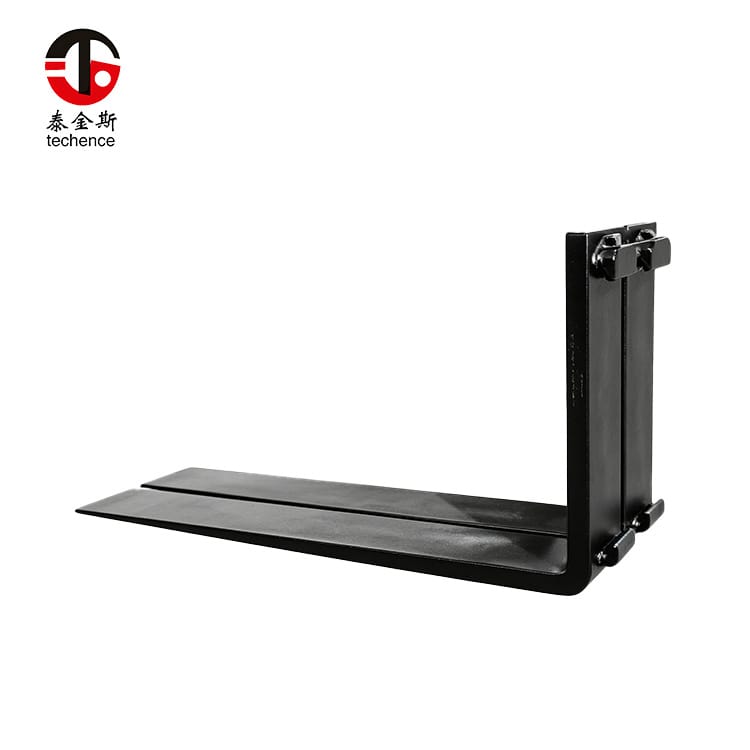
Forklift forks are essential during load handling, but their full blade length can become a disadvantage when the machine is traveling without a load, being transported, parked in a compact area, or maneuvered through a restricted route.
Fixed forks continue to project from the front of the machine even when they are not in use. This projection increases the equipment’s overall operating envelope and may complicate turning, storage, transport, doorway access, and attachment changes.
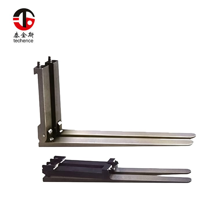
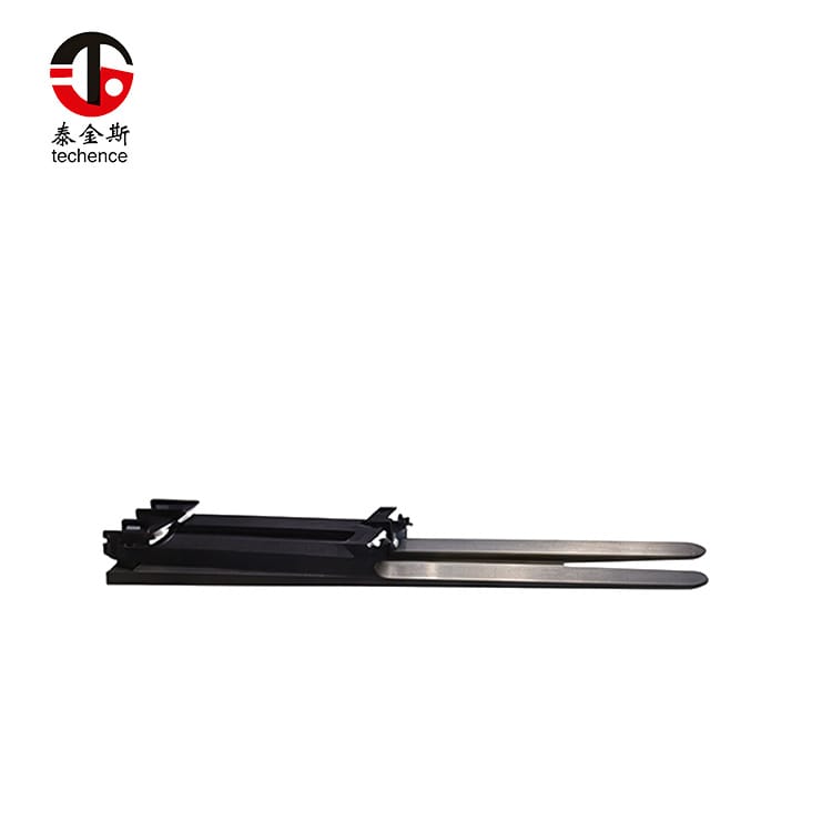
Folding forks address this problem by allowing the horizontal blade to pivot upward around a reinforced hinge. In the folded position, the blade is secured close to the fork shank or carriage, reducing the amount of unsupported fork length extending in front of the equipment.
The folding function can improve non-working maneuverability, but it also introduces additional engineering considerations. The hinge pin, locking device, retaining components, blade alignment, fork capacity, carriage mounting, and folded clearance must all be evaluated.
Key points covered in this article include:
- How folding forks operate
- Where the design creates practical value
- How the hinge transfers load
- What must be measured before selection
- How folding forks compare with alternative fork systems
- Which locking and retaining features need inspection
- How to conduct a controlled operational trial
- Which maintenance mistakes can shorten service life
The following analysis uses a representative material-handling scenario rather than claiming results from a specific customer project.
What Are Folding Forks?
Folding forks are specialized forklift forks with a hinged connection between the blade and the upright fork section.
A conventional fork is normally formed as a continuous L-shaped component. Its blade extends horizontally beneath the load, while its shank connects the fork to the carriage. Folding forks divide this structure into connected sections so the blade can pivot upward when it is not carrying a load.
A typical folding fork assembly may include:
- Horizontal fork blade
- Vertical shank
- Hinge lugs or connecting plates
- Hinge pin
- Pin retainers
- Operating-position lock
- Folded-position restraint
- Carriage hooks or shaft mounting
- Fork-position lock
- Identification and capacity markings
Folding forks should not be confused with a hinged carriage attachment that tilts the entire fork assembly forward. With folding forks, the individual fork blades pivot around a hinge near the heel area.
Operating Position
In the operating position, the blade is lowered into its approved horizontal position and secured according to the design.
The load path then runs from the blade through the hinge area, shank, mounting interface, carriage, mast, and forklift structure.
The hinge is not inactive during lifting. It is part of the structural system and must resist the forces created by the load.
Folded Position
In the folded position, the blade is raised toward the shank or carriage.
The blade must be held by a suitable restraint, such as a locking pin, clamp, chain, retaining bracket, or another approved device. The exact system depends on the folding fork design.
A blade should never be left partially raised or unsecured. Machine movement, vibration, slope, or accidental contact could cause an uncontrolled change in blade position.
Folding Is a Non-Load Function
The folding operation is normally intended for an unloaded fork.
The load should be removed, the equipment placed in a controlled condition, and the blades positioned according to the manufacturer’s procedure before folding begins.
Folding forks are not intended to pivot upward while supporting cargo unless a specific engineered design expressly provides that function.
Representative Application Study
Consider a material-handling operation using a lift machine that performs two distinct tasks:
- It lifts palletized or framed equipment at a work area.
- It frequently travels, parks, or is transported without carrying a load.
The fixed fork blades are necessary during lifting, but their full length provides no benefit during non-load movement.
The Original Operating Problem
With fixed forks installed, the machine’s front projection remains unchanged throughout the day.
This creates several practical issues:
- More space is required when turning
- The tips can extend into pedestrian or equipment routes
- Parking areas must accommodate the complete blade length
- Transport platforms need additional clearance
- Attachment storage becomes more difficult
- Doorway and workshop access may be restricted
- The operator must remain aware of blade tips that may be difficult to see
Removing the forks could reduce the projection, but frequent removal requires lifting equipment, storage space, installation time, and repeated mounting inspection.
The Folding Fork Alternative
Folding forks retain the load-handling function while allowing the blades to be raised when the machine is not working with a load.
The revised process becomes:
- Complete the load-handling task.
- Lower the forks to a controlled position.
- Confirm that the blades are unloaded.
- Stop and secure the equipment according to the operating procedure.
- Release the approved folding mechanism.
- Raise each blade.
- Secure the blades in the folded position.
- Verify clearance before moving the machine.
The machine can then travel or be stored with a reduced front projection.
Operational Benefits
The main benefit is not increased lifting capacity. It is improved equipment configuration when the blades are not required.
Potential advantages include:
- Reduced non-working front projection
- Easier maneuvering in restricted areas
- More compact parking and storage
- Simpler equipment transport
- Lower risk of an unseen blade tip extending into a route
- Less need to remove and reinstall forks
- Faster transition between working and transport configurations
These advantages are only realized when the folding and locking procedure is simple enough to follow consistently.
New Controls Introduced by the Folding Design
The operation must now manage additional items:
- Hinge-pin condition
- Locking-device engagement
- Folded-position restraint
- Blade alignment after lowering
- Hinge contamination
- Side clearance
- Pin-retainer condition
- Operator folding procedure
- Inspection after impact
The case therefore changes one operational challenge into a more manageable but more technically controlled system.
Where Folding Forks Provide the Most Value
Folding forks are most useful when reducing front projection solves a repeated operational problem.
Equipment Transport
Lift machines may need to be transported between work areas on a vehicle, platform, or other transport system.
Fixed forks can increase the overall transport length and require more space around the machine. Folding the blades may create a more compact configuration.
Before transport, confirm:
- Both blades are fully raised
- Each restraint is engaged
- The blades cannot swing
- The folded blades do not interfere with the cab or mast
- Transport tie-downs do not damage the forks
- The complete machine remains within the approved transport arrangement
Folding the blades does not replace the need to secure the machine itself.
Confined Storage Areas
Equipment stored in workshops, service areas, machinery rooms, or compact yards may have limited floor space.
Raised blades can reduce the space occupied in front of the carriage. This may allow equipment to be parked without removing the forks.
The folded blades should not obstruct:
- Operator access
- Emergency exits
- Visibility
- Mast movement
- Hydraulic hoses
- Maintenance points
- Other attachments
Narrow Access Routes
A long fork blade reaches a corner before the machine body. This can make restricted turns more difficult.
Folding forks can improve non-load access through:
- Narrow doors
- Short turning areas
- Compact service corridors
- Equipment staging areas
- Restricted loading platforms
- Congested work zones
The machine’s width, height, turning radius, counterweight, and mast still determine whether the route is suitable.
Machines with Interchangeable Tools
Some lift machines change between forks, buckets, platforms, clamps, or other working tools.
A folding fork carrier can sometimes remain attached while the blades are raised, allowing the machine to reduce its front projection without completely removing the fork assembly.
The compatibility of the folded blades with other tools must be confirmed. The blades should not contact the attachment, hydraulic connections, quick coupler, or ground.
Frequent Non-Load Travel
The more frequently a machine moves without cargo, the greater the potential value of a compact fork position.
A machine that handles pallets continuously may gain little from the folding function. A machine that performs short lifting tasks followed by frequent relocation may benefit significantly.
When Folding Forks May Not Be the Best Choice
A folding design is not automatically better than a fixed fork.
Continuous Pallet Handling
In a warehouse or production line where the forks remain in use throughout the shift, the blades may rarely need to be raised.
Fixed forks provide a simpler structure with fewer moving and locking components.
Severe Impact Applications
Repeated impact around the fork heel can place additional demand on the hinge, pin, lugs, and locks.
Where operators frequently strike skids, floors, loading platforms, or load frames, the operation should first address visibility, access, training, and load-entry conditions.
A folding mechanism should not be used to compensate for uncontrolled impact.
Highly Contaminated Environments
Mud, fibers, dust, loose packaging, abrasive particles, and corrosive material can accumulate around the hinge.
Folding forks may still be suitable, but cleaning and inspection intervals will need to reflect the environment.
Loads Requiring Maximum Structural Simplicity
Certain severe applications may favor a continuous forged heel without a movable joint.
The choice should be based on load analysis, duty cycle, shock exposure, and the validated capacity of the proposed fork.
Poor Locking Discipline
A folding system is unsuitable when operators are unlikely to verify the operating-position lock or folded-position restraint.
A correctly manufactured fork can still be used incorrectly. The locking sequence must be clear, repeatable, and included in operator training.
How Folding Forks Work
The hinge mechanism is the main feature distinguishing folding forks from standard fixed forks.
Blade Hinge
The blade hinge allows the horizontal section to rotate relative to the shank.
Depending on the design, the hinge may use:
- Inner connecting lugs
- Outer connecting plates
- Single-pin suspension
- Double-pin arrangements
- Locked operating positions
- Free movement in a defined working position
The hinge layout influences fork width, load path, folded clearance, manufacturing complexity, and capacity.
Hinge Pin
The hinge pin supports the relative movement between the blade and shank.
It must match:
- Pin diameter
- Bearing length
- Lug dimensions
- Material specification
- Surface treatment
- Retaining method
- Lubrication requirement
- Permitted clearance
The pin should not be replaced with an unverified general-purpose fastener.
Operating-Position Lock
The blade must remain in the intended working position during fork entry, lifting, travel, and unloading.
The lock may use:
- Mechanical bolt
- Safety clamp
- Retaining pin
- Shaped stop
- Double-pin system
- Integrated locking plate
The lock should engage fully without requiring unapproved force, grinding, spacing, or modification.
Folded-Position Restraint
Once the blade is raised, another device prevents it from falling.
This restraint may be a chain, pin, bracket, clamp, latch, or other mechanical feature.
It should be:
- Easy to inspect
- Protected against accidental release
- Strong enough for vibration and movement
- Positioned without damaging the blade
- Replaceable when worn
- Compatible with the complete folded envelope
Manual Folding
Many folding forks are raised manually. This means blade weight and handling position matter.
The operation should consider:
- Whether one person can safely control the blade
- Whether a lifting aid is required
- Where the operator stands
- Pinch points around the hinge
- How the blade is restrained during movement
- Whether the machine must be tilted or lowered
- How the lock is accessed
The procedure should avoid placing hands between the blade, shank, carriage, or locking components.
Folding Forks vs Other Fork Solutions
| Fork Solution | Primary Function | Non-Working Length | Main Advantage | Main Limitation |
|---|---|---|---|---|
| Folding forks | Lift loads and fold blades upward when unloaded | Reduced when folded | Compact travel, storage, and transport configuration | Adds hinges, pins, locks, and inspection points |
| Fixed forks | General load lifting | Full blade length remains | Simple and direct load path | Permanent front projection |
| Removable forks | Forks can be detached from the carriage | Reduced after removal | Removes the complete blade and shank | Requires handling equipment, storage, and reinstallation |
| Fork extensions | Temporarily increase blade length | Full extension length remains until removed | Supports approved longer loads | Does not reduce the original fork projection |
| Telescopic forks | Extend and retract hydraulically or mechanically | Can retract to a shorter working length | Adjustable reach for deep loads | More complex, heavier, and dependent on the extension mechanism |
| Quick-change fork carrier | Allows the complete carrier to be exchanged | Depends on the installed tool | Supports multiple attachments | Requires compatible coupler and attachment storage |
| Hinged carriage | Tilts the complete carriage or fork assembly | Fork length remains | Changes load-dumping or positioning angle | Does not fold individual fork blades vertically |
The correct solution depends on the actual problem.
Folding forks are suitable when the equipment needs ordinary fork functionality during work but a shorter non-working configuration during travel, storage, or transport.
Match Folding Forks to the Load
The folding function should never distract from the fork’s primary purpose: supporting the load.
Maximum Load Weight
Record the complete maximum load, including:
- Product
- Pallet
- Skid
- Frame
- Packaging
- Fixtures
- Retained material
- Accessories
Use the highest approved operating load rather than an average value.
Load Center
The load center is the horizontal distance between the relevant fork reference point and the load’s center of gravity.
As this distance increases, the forward load moment also increases.
The hinge, blade, shank, carriage, mast, and forklift must all be suitable for the defined load-center condition.
Load Dimensions
Measure:
- Load width
- Load depth
- Load height
- Pallet opening
- Required insertion depth
- Position of support points
- Permitted blade projection
- Center-of-gravity position
Fork length should provide appropriate support without being unnecessarily long.
Fork Spacing
The forks should be positioned beneath stable support points.
Incorrect spacing can create:
- Unequal load distribution
- Poor lateral stability
- Pallet damage
- Increased stress on one fork
- Difficulty entering the load
- Interference when folding
The folded blades must also clear each other and the surrounding carriage structure.
Offset Loads
An off-center load can place more force on one folding fork and one side of the carriage.
The operation should not assume that a stated pair capacity permits one blade to carry most of the load.
Verify Forklift and Carriage Compatibility
Folding forks are not universal.
A forklift carries its forks or attachments on a carriage connected to the mast. Fork dimensions, mounting, weight, and load position affect the complete machine configuration.
Carriage Class
For hook-mounted forks, confirm:
- Carriage class
- Upper carriage-bar dimensions
- Lower carriage-bar position
- Hook opening
- Shank height
- Lock-pin position
- Side clearance
- Carriage width
A model description alone may not identify the installed carriage, especially when a mast or fork carrier has been replaced.
Shaft or Pin Mounting
Some folding forks use a shaft, pin, or custom carrier.
Verify:
- Shaft diameter
- Fork-eye diameter
- Eye width
- Mounting spacing
- Retaining components
- End stops
- Positioning system
- Side clearance
Folded Clearance
Measure the blade path from the horizontal working position to the fully raised position.
Check for interference with:
- Mast channels
- Carriage
- Load backrest
- Hydraulic hoses
- Cylinders
- Cab
- Windshield
- Boom structure
- Work lights
- Other attachments
- The second fork blade
Checking only the final folded position is not enough. The blade must clear surrounding components throughout the complete arc.
Ground and Transport Clearance
The folded blade should remain secure during:
- Turning
- Braking
- Surface changes
- Equipment transport
- Loading onto a platform
- Parking on a slope
- Attachment changes
The folded tips should not project into the operator area or beyond the approved machine envelope.
Evaluate the Hinge and Locking System
The hinge and locks distinguish a dependable folding design from a fork that is merely capable of moving.
Hinge-Pin Support
The pin needs sufficient support length and suitable contact with the hinge lugs.
Excessive clearance may allow:
- Blade movement
- Impact loading
- Uneven pin wear
- Misalignment
- Locking difficulty
- Increased stress around the lugs
Insufficient clearance can cause binding, especially after contamination or deformation.
Hinge-Lug Geometry
The hinge lugs transfer load between the blade and shank.
Inspect:
- Lug thickness
- Pin-hole alignment
- Welded or forged transitions
- Surface condition
- Edge radius
- Side spacing
- Signs of spreading
- Cracks around pin holes
Operating Stops
The blade may rest against a structural stop in the working position.
The stop should contact evenly across the intended surfaces. Localized contact can create high stress and rapid wear.
Lock Engagement
A lock should have a clear engaged and disengaged condition.
Operators should be able to confirm engagement visually or physically without guessing.
Partial engagement should be treated as an unsafe condition.
Retaining Components
Pin clips, bolts, chains, latches, clamps, and retainers should be included in the inspection program.
A small missing retainer can allow a major pin or locking component to move out of position.
Protection Against Unintended Folding
The design must prevent the blade from folding during normal load handling.
Protection may come from:
- Positive mechanical locking
- Load-bearing stops
- Double-pin arrangements
- Safety bolts
- Retaining clamps
- Controlled hinge geometry
Relying only on blade weight is not sufficient.
Understand Capacity and the Load Path
Folding forks introduce a joint into an otherwise continuous fork form.
This does not automatically make them unsuitable, but it changes how the structure must be evaluated.
Blade Load
The load first acts on the horizontal blade.
The blade experiences bending based on:
- Load weight
- Load position
- Blade length
- Blade section
- Support-point width
- Fork spacing
- Dynamic movement
Hinge Load
The hinge transfers forces between the blade and the shank.
The pin, lugs, stops, and locks must function together. Evaluating only the pin diameter is insufficient.
Shank and Mounting Load
The shank transfers force into the carriage through hooks, pins, shafts, or another mounting system.
Wear at the carriage can allow movement that increases impact around the folding joint.
Fork Weight
The hinges, lugs, pins, and locking components add weight.
This weight becomes part of the load carried in front of the forklift and should be included in the residual-capacity review.
Residual Capacity
Residual capacity depends on the complete configuration, including:
- Folding fork weight
- Blade length
- Load center
- Mast type
- Lift height
- Carriage
- Other attachments
- Forklift rating
- Load dimensions
A folding fork rating does not increase the approved capacity of the forklift.
Evaluate Material and Manufacturing Quality
The hinge is only one part of product quality.
Fork Steel
The material should provide a suitable balance of:
- Strength
- Toughness
- Fatigue resistance
- Impact tolerance
- Heat-treatment response
- Wear resistance
An excessively hard component may be less tolerant of impact, while insufficient strength can allow permanent deformation.
Forging and Forming
The blade and shank should have controlled geometry and a consistent load-bearing section.
The folding forks product range can be evaluated by load requirement, installation class, blade dimensions, hinge arrangement, and customization needs.
When the folding components are welded to a forged or formed fork section, the welded transitions need suitable design and manufacturing control.
Heat Treatment
Heat treatment influences strength, toughness, hardness, and fatigue behavior.
Large section differences around the blade, shank, and hinge lugs require attention to distortion and consistency.
Machining Accuracy
Machined hinge surfaces determine pin fit and blade alignment.
Important characteristics include:
- Pin-hole diameter
- Hole alignment
- Surface finish
- Side clearance
- Parallelism
- Pin-retainer position
- Locking-hole alignment
Poor alignment can cause binding or uneven load transfer.
Fork-Pair Consistency
The left and right folding forks should match in:
- Blade length
- Blade section
- Tip height
- Hinge position
- Hinge clearance
- Shank angle
- Hook position
- Folded height
- Locking arrangement
An unmatched pair may support the load unevenly or fold into different positions.
Use the FOLD Selection Framework
The following original framework organizes the main selection requirements.
F: Function and Load
Define:
- Maximum load
- Load center
- Load dimensions
- Fork spacing
- Required blade length
- Number of handling cycles
- Type of pallet or support
- Need for folding
The folding function should solve a real operational problem.
O: Operating Envelope
Measure:
- Available turning space
- Doorway dimensions
- Parking area
- Transport platform
- Storage position
- Folded blade height
- Complete folding arc
- Mast and cab clearance
- Nearby attachment clearance
Both the working and folded configurations must fit the operation.
L: Locking and Load Path
Verify:
- Hinge design
- Pin dimensions
- Hinge-lug construction
- Working-position stop
- Operating lock
- Folded-position restraint
- Carriage mounting
- Residual capacity
- Protection against unintended movement
D: Duty Cycle and Documentation
Review:
- Operating frequency
- Impact exposure
- Contamination
- Inspection interval
- Lubrication requirements
- Wear limits
- Material records
- Capacity markings
- Installation instructions
- Folding procedure
- Replacement-part availability
All four elements should be complete before the forks enter normal service.
Conduct a Controlled Operational Trial
A controlled trial verifies the entire working and folding sequence.
Test the Working Position
Use representative approved loads and observe:
- Fork entry
- Full insertion
- Load support
- Blade alignment
- Hinge movement
- Lock engagement
- Fork deflection
- Carriage movement
- Visibility
The blades should remain stable without unusual noise or movement.
Test the Initial Lift
Raise the load only enough to confirm:
- Both forks carry evenly
- The locks remain engaged
- The hinge does not move unexpectedly
- The load is centered
- The carriage remains stable
- The blade stops contact correctly
Test the Folding Procedure
After unloading:
- Lower the forks.
- Secure the machine.
- Confirm that the blades are unloaded.
- Release the approved folding lock.
- Raise the blade using the defined method.
- Engage the folded-position restraint.
- Verify each blade independently.
- Check the complete machine envelope.
Observe whether the operator must adopt an awkward posture or enter a pinch zone.
Test Folded Travel
Move the unloaded machine through the intended route at a controlled speed.
Check:
- Blade restraint
- Vibration
- Blade clearance
- Turning space
- Doorway clearance
- Visibility
- Contact with hoses or structures
- Noise from the hinge or locks
Test Transport and Storage
Confirm that the folded machine fits:
- Parking areas
- Storage bays
- Service locations
- Transport platforms
- Attachment-change zones
The blade restraints should remain accessible for inspection.
Inspect After the Trial
After repeated cycles, inspect:
- Hinge pins
- Pin retainers
- Lugs
- Working stops
- Operating locks
- Folded restraints
- Blade alignment
- Carriage hooks
- Surface contact marks
A successful design should perform consistently, not only during one cycle.
Inspect Folding Forks Before Use
A daily inspection should cover both ordinary fork areas and folding-specific components.
Blade and Tip
Look for:
- Bending
- Twisting
- Cracks
- Gouges
- Tip damage
- Wear
- Unequal fork height
- Permanent deformation
Hinge Area
Inspect:
- Hinge lugs
- Pin holes
- Connecting plates
- Working stops
- Welded transitions
- Surface cracks
- Spreading
- Deformation
- Uneven contact
Hinge Pin
Check for:
- Side movement
- Rotation where it should not occur
- Scoring
- Corrosion
- Bending
- Missing retainers
- Uneven wear
- Lubrication condition
Locking System
Confirm that:
- The lock engages completely
- Pins are present
- Clamps close correctly
- Safety bolts are installed
- Chains are undamaged
- Retainers are secure
- The lock cannot release accidentally
Carriage Interface
Inspect:
- Hooks
- Shaft eyes
- Lock pins
- Carriage bars
- End stops
- Side clearance
- Mounting movement
Fork-Pair Alignment
Compare both forks in the lowered and folded positions.
Differences may indicate hinge wear, blade deformation, pin wear, carriage damage, or an unmatched fork pair.
Maintain Folding Forks
Maintenance should preserve both structural integrity and free, controlled folding movement.
Clean the Hinge
Remove:
- Dust
- Fibers
- Plastic film
- Grease contamination
- Corrosive deposits
- Metal particles
- Mud
- Packaging debris
Cleaning should not force contamination deeper into the pin area.
Control Lubrication
Use the specified lubricant and application interval.
Too little lubrication can increase wear and binding. Excessive lubrication can attract abrasive contamination.
Monitor Hinge Clearance
Measure side and pin clearance at consistent points.
An increase over time may reveal:
- Pin wear
- Lug wear
- Retainer movement
- Misalignment
- Impact damage
Replace Worn Retainers
A worn chain, clip, bolt, clamp, or safety pin should not be treated as a minor defect.
The restraint should be restored with a verified compatible part.
Protect Folded Blades
When stored, folded blades should not rest against surfaces that damage the tips, edges, or restraints.
External loads should not be placed against raised blades.
Investigate Impact
After severe impact, inspect the complete system before returning it to normal use.
Damage may affect:
- Blade
- Hinge
- Pin
- Lugs
- Stops
- Locks
- Shank
- Carriage
Common Folding Fork Selection Mistakes
Choosing by Capacity Alone
Capacity does not confirm folded clearance, hinge design, mounting, blade length, or operating procedure.
Failing to Measure the Folding Arc
A blade may fit in the final raised position but strike a hose, mast, backrest, or cab while moving upward.
Ignoring Blade Weight
A manually folded blade may require more controlled handling than expected.
The folding procedure should be reviewed before installation.
Treating the Hinge as a Convenience Feature
The hinge is a load-bearing assembly. Its design, material, pin, locks, and stops require the same attention as the fork blade.
Failing to Secure Raised Blades
A folded blade should never rely on balance or friction to remain upright.
Folding While Loaded
The load must be removed before the blade is folded unless the product documentation expressly provides another approved procedure.
Using Worn Locks
A partially engaged or loose lock can allow unexpected movement.
Ignoring Carriage Interference
Raised blades may contact the mast, backrest, hoses, or another attachment.
Replacing Only One Fork
A replacement should match the remaining fork in:
- Capacity
- Blade section
- Length
- Hinge position
- Mounting
- Tip height
- Folded height
- Locking system
- Wear condition
Folding Fork Specification Checklist
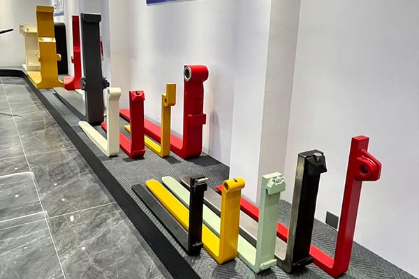
Before requesting folding forks, collect the following information.
Forklift Information
- Manufacturer and model
- Equipment identification
- Rated capacity
- Rated load center
- Mast type
- Maximum lift height
- Carriage class
- Carriage dimensions
- Load backrest dimensions
- Installed attachments
- Previous modifications
Load Information
- Maximum load weight
- Load width, depth, and height
- Center-of-gravity position
- Pallet or skid dimensions
- Fork-entry dimensions
- Required fork spacing
- Handling frequency
- Required lift height
Fork Information
- Blade length
- Blade width
- Blade thickness
- Shank dimensions
- Mounting type
- Hook or shaft dimensions
- Hinge type
- Locking arrangement
- Folded height
- Blade weight
- Required surface treatment
Operating-Envelope Information
- Doorway dimensions
- Turning space
- Storage area
- Transport platform
- Cab clearance
- Mast clearance
- Hydraulic-hose position
- Attachment-change procedure
- Ground conditions
- Folding frequency
When a standard configuration cannot satisfy the required load, mounting, or folded envelope, a custom folding fork specification review should include drawings, measurements, load photographs, carriage information, and the complete working and folding sequence.
Conclusion
Folding forks are designed for operations that need full-length fork blades during material handling but a more compact machine configuration during non-load travel, transport, parking, or storage.
Their value is greatest when fixed blades create a repeated maneuvering or space problem. The folding function can reduce front projection without requiring the complete fork assembly to be removed.
However, folding forks are not simply standard forks with a movable blade. They introduce a load-bearing hinge, pin, stop, operating lock, and folded-position restraint.
A dependable selection process should:
- Define the load and load center.
- Verify forklift and carriage compatibility.
- Measure the complete folding arc.
- Confirm mast, cab, hose, and backrest clearance.
- Evaluate the hinge and locking system.
- Include fork weight in the residual-capacity review.
- Test both working and folded configurations.
- Inspect the pin, lugs, locks, and retainers regularly.
The best folding forks are those that remain fully stable during load handling, fold through a clear and controlled path, lock securely in both required positions, and provide a genuine improvement in the machine’s non-working operating envelope.
FAQ
What are folding forks used for?
Folding forks are used where full-length fork blades are required for lifting but create unnecessary projection during travel, transport, parking, or storage. Their hinged blades fold upward when unloaded, allowing the machine to use less space without removing the complete fork assembly.
Can folding forks lift the same loads as fixed forks?
Capacity depends on the blade section, hinge construction, pin, locks, mounting, load center, fork length, and documented rating. A folding design should be selected from its verified capacity data rather than assumed to match a fixed fork with similar external dimensions.
How are folding forks secured in the raised position?
The blades may use chains, clamps, locking pins, safety bolts, brackets, or other approved restraints. The restraint must engage fully and prevent the blade from falling during vibration, turning, storage, or transport. The exact procedure depends on the fork design.
Can folding forks fit any forklift?
No. The mounting system, carriage class, shank dimensions, fork spacing, folded height, blade path, mast clearance, and residual capacity must match the forklift. The complete folding arc should be checked because a blade may interfere before reaching its final position.
What parts of folding forks require the most inspection?
Inspect the blades, hinge lugs, hinge pins, pin retainers, operating stops, working-position locks, folded-position restraints, shanks, mounting hooks, and carriage. Increasing hinge clearance, incomplete lock engagement, cracks, deformation, or missing retainers require immediate evaluation.